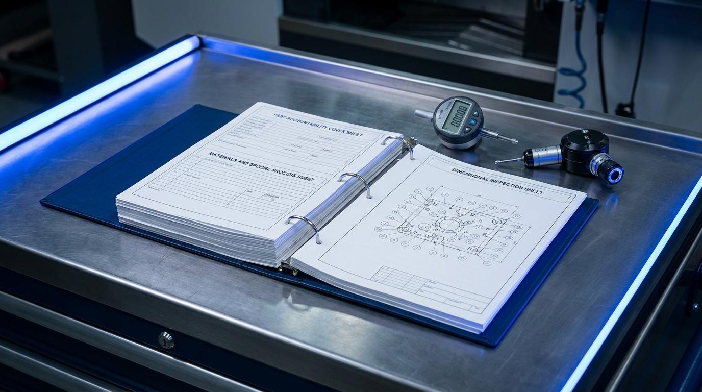

First Article Inspection Report Rejected: Where the AS9102 Chain Actually Breaks
"CMM: all green, Reality: failed. What did the CMM NOT catch?" a CNC milling practitioner posted online, describing a part that passed every programmed measurement and still did not work in the assembly. In a related discussion, a self-described third-tier supplier put the constraint plainly: "If you're a 3rd tier supplier, the print is all you likely have to work from." Three tiers down from the customer who wrote the drawing, the print is the entire contract, and the print is frequently ambiguous about exactly the thing that later fails.
Those two lines describe the same underlying problem from opposite ends. The CMM measured what it was programmed to measure and the part still failed, because the program answered a different question than the one the drawing was actually asking. The supplier who only has the print has no way to resolve that ambiguity before it becomes a rejected First Article Inspection. Between those two moments, drawing intent and CMM output, sits a chain: a characteristic gets identified on the drawing, ballooned, tied to a requirement, measured, recorded on Form 3, and finally covered by the signature on Form 1. An AS9102 binder comes back almost every time because one link in that chain broke quietly, not because a whole document went missing. Here are six of the places it breaks, in a practitioner's own words, what AS9102 Rev C actually requires at that link, and what the platform does, and in two cases does not yet do, about it.
"A plug gauge only checks the maximum inscribed, it doesn't check envelope"
A manufacturing consultant wrote that line in a discussion about a hole callout that carried a size tolerance and a position tolerance with a material-condition modifier. A plug gauge answers one question: does the hole clear the maximum-material boundary. A CMM measuring least-squares circle fit can answer a different question about the same hole. Two accepted measurement methods, two different answers, and the drawing's feature control frame is the only place that says which one the print is actually asking for.
AS9102 Form 3 requires a measurement method next to every result, precisely because this ambiguity is common enough to be a standard clause, not an edge case. The reviewer checks whether the recorded method matches what the feature control frame calls for. What the site does: extraction reads the material-condition modifier, MMC or LMC, off the feature control frame and carries it as structured data on the characteristic record, not flattened into a text approximation, so the requirement Form 3 renders is the real symbol with its real modifier circled, the same frame the drawing shows. What it does not do: nothing in the characteristic record captures which measurement method or fit algorithm, max inscribed, least squares, two-point, actually produced a given result. The requirement is captured correctly; the method used to verify it still lives only in the inspector's head, which is exactly the gap a reviewer who has seen this fail before is trained to ask about.
"If multiple inspectors dont know how to read the MMC modifier"
Another engineer replied in the same kind of thread, naming the failure mode from the other direction: an inspector who cannot read a material-condition modifier at all. A balloon on a drawing that carries an MMC symbol, misread as an ordinary size tolerance, produces a measurement against the wrong limit, or no measurement at all if the inspector defers the row rather than guess.
What AS9102 requires here is a one-to-one mapping: every ballooned characteristic gets a Form 3 row with an actual result. What the reviewer checks first is exactly that mapping, a balloon on the print with no corresponding row, or a row with no result behind it. What the site does: because the feature control frame renders as drawn geometry rather than an ASCII approximation, the modifier an inspector needs to read is the real circled letter on the export, in both the PDF and the Excel workbook, not a transcription an inspector has to decode from a text string. What happens when a characteristic genuinely has no result on record is also honest rather than papered over: the Results cell renders blank, on purpose, "the AS9102 convention for an unmeasured first article," so a missing measurement shows up as a visibly empty cell on the binder rather than a plausible-looking placeholder. A reviewer scanning for gaps sees the actual gap.
"A bolt circle that was positional in tolerance yet was rotated 2 degrees"
One quality engineer described a part where the position tolerance on a bolt circle passed clean, and the part still would not assemble, because the whole pattern was rotated two degrees relative to the mating part. In tolerance and wrong function are not the same thing, and AS9102 Form 3 was never built to distinguish them. The form asks for a requirement and a result, dimension against tolerance. It has no column for "does this pass and still not work."
That is a limitation of the standard's own form, not something a platform checks its way around, and it is worth naming directly. The characteristic record this platform generates carries exactly what Form 3 asks for: a nominal, a tolerance, and a measured result. It cannot know that a rotated bolt pattern is a functional problem the drawing's tolerancing scheme failed to constrain. A rotated-but-in-tolerance failure is caught by design review and composite tolerancing, not by an inspection record; a binder full of passing Form 3 rows is evidence the part matches the drawing, never proof the drawing fully specified the function.
"Datum selection becomes key"
An inspector wrote that line describing a program where the primary datum was argued in meetings more than once, because the print's datum reference frame was ambiguous enough that two reasonable engineers picked different primary datums for the same feature. A setup built against the wrong datum measures the right dimension against the wrong reference, and every result that follows from it is quietly invalid even though every individual number looks fine.
AS9102 does not audit the datum scheme itself; it assumes the FAI setup matches the drawing's datum reference frame and records results against that assumption. What the site captures: each datum reference on a feature control frame, including its own material-condition modifier, is read and stored as structured data per characteristic, not merged into a single opaque tolerance string, so the datum scheme on record for a given requirement is the same one drawn on the print, cell by cell, in the order the print specifies it (primary, secondary, tertiary). What it does not yet do: there is no field or check tying a specific inspection record to the physical datum scheme the fixture actually used at the time of measurement, so a fixture built against the wrong datum would not be caught automatically. The record faithfully carries what the drawing says the datums are; it does not verify that the shop floor set up against them.
Form 1 locked before Forms 2 and 3 were complete
AS9102 Rev C's own integrity rule is that signing Form 1 locks the whole FAIR: Form 2 and Form 3 no longer carry their own signature blocks, and the Form 1 signature is the single point of accountability for the package underneath it. A source inspector who trusts a signed Form 1 is trusting that Forms 2 and 3 behind it are actually complete.
Here is the honest state of the export path today: nothing in it blocks generating or signing Form 1 while Form 2 or Form 3 still has incomplete rows. The one integrity behavior that does exist is narrower and different: the packaged FAIR export never fabricates a form that does not exist, it simply omits whatever has not been built yet, so an incomplete package cannot accidentally look complete by having a form invented for it. That is a real guardrail against one failure mode, a phantom Form 2, and not a guardrail against the failure mode Rev C's own signature-lock rule is actually worried about, a real Form 1 signed while a real Form 2 or Form 3 is thin. A reviewing quality engineer should treat the Form 1 signature the same way regardless: as an attestation a human made, not a state the software enforced.
Partial versus full re-accomplishment when the drawing changes
The trigger for this whole conversation is usually a drawing revision. AS9102 Clause 4 (covered in full, with its four triggers and the impact-analysis discipline, in AS9102 Partial FAI Re-accomplishment) asks the supplier to decide, and defend, whether a change requires re-verifying the whole part or only the characteristics the change actually touched.
What the site does at this link in the chain is a concrete mechanic, not just a documentation pattern. When an Engineering Change is opened against a part, the change record derives an affected-characteristic set specific to the change type: for a design-record change, that set comes from diffing the old and new drawing extractions and mapping the delta to the changed or added balloons. A one-click "Delta FAI" action on that Engineering Change then creates a scoped inspection run, marked as an AS9102 FAI, covering only the affected characteristics, and links it back to the original run it was spawned from so an auditor can trace the lineage from the new partial to the FAI it partially replaces. The Engineering Change record itself carries a forward link to that scoped run, so a reviewer opening the change sees, without hunting, whether a re-inspection was ever created for it. This is the drawing-to-Form-3 chain rebuilding itself automatically at the one point, a revision, where suppliers most often either over-scope a full re-accomplishment they did not need or under-scope a partial that misses a downstream characteristic.
The chain, not the checklist
None of the six breaks above is solved by a longer checklist. A checklist confirms every box got touched; it does not confirm that the plug gauge answered the same question the drawing asked, that the modifier an inspector read matched the one on the frame, or that the datum a fixture used was the datum the print specified. Those are chain problems, and the chain either holds from the drawing through to the Form 1 signature or it does not.
Two of the six sections above named a real gap rather than a feature: no field yet records which measurement method verified a characteristic, and nothing yet blocks a Form 1 signature ahead of incomplete Form 2 or Form 3 rows. Naming those honestly is the same discipline this cluster has followed since PPAP Rejection Reasons and How to Catch Them: a tool that tells you where it does not yet check is more useful than one that implies it checks everything. For the form-by-form mechanics this post assumes, see AS9102 First Article Inspection: Form 1, Form 2, and Form 3, Form 1 Part Number Accountability, Form 2 Product Accountability, and Form 3 Dimensional Results. The ballooning discipline every one of these chain breaks depends on is in Characteristic Accountability in AS9102, and the drawing-to-characteristic-list extraction that starts the whole chain is in AI GD&T Extraction. If your shop runs both AS9102 and AIAG PPAP on the same part, FAI vs PPAP covers where the two submissions share evidence and where they diverge, and suppliers coming from AIAG APQP will want AS9145 Aerospace APQP and PPAP as a field map.
If you want to see the chain built against your own drawing, from balloon to Form 3 to a signed Form 1, start a trial on the Build module. Blueprint Intelligence is the extraction step that reads the feature control frames, datums, and modifiers described above straight off a digital drawing, so the characteristic list a binder stands or falls on comes from the print itself.