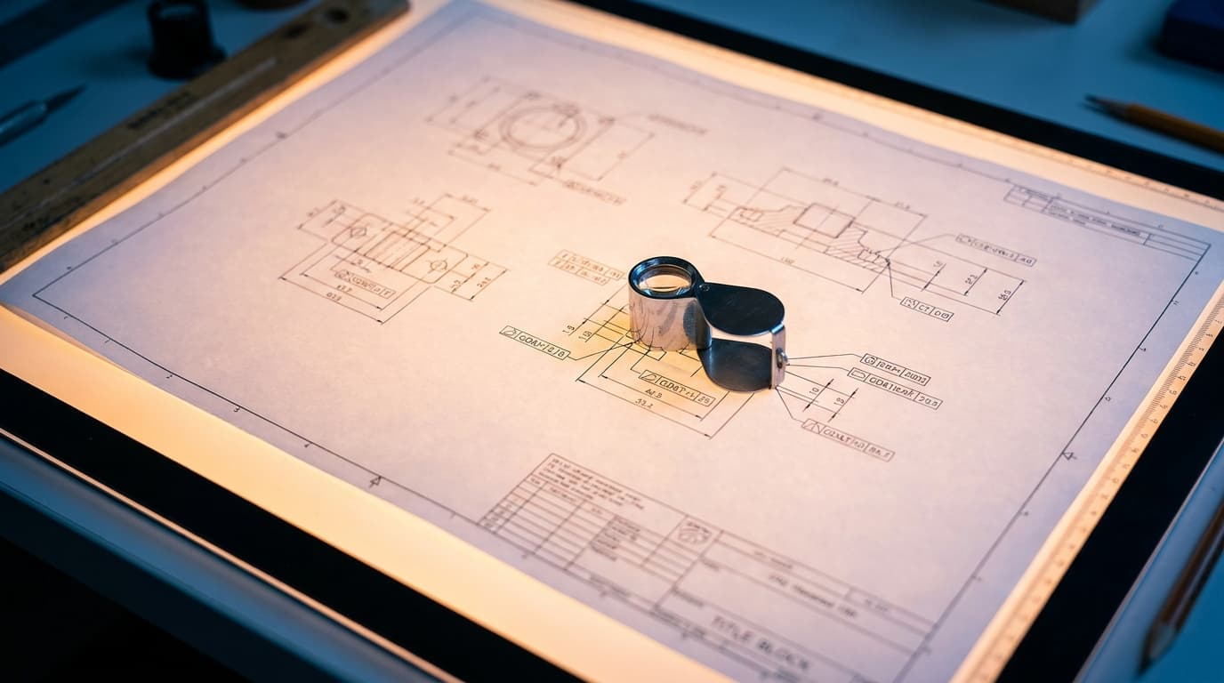
A new drawing revision comes in from engineering at 4pm on a Tuesday. Rev B to Rev C on a wheel hub. Before anyone can touch the Control Plan or start the PFMEA, someone has to open the PDF, find every dimension, read every GD&T feature control frame, note the datum references, flag which characteristics carry the diamond or the SC/CC marker, and type all of it into a spreadsheet or a balloon log by hand. On a drawing with forty callouts, that is an afternoon of transcription before the actual quality engineering work even starts. Miss one feature control frame buried in a section view and it does not show up in the PFMEA, does not get a control method, and does not get inspected, until a customer finds it on incoming or a CMM report comes back with no corresponding spec to check it against.
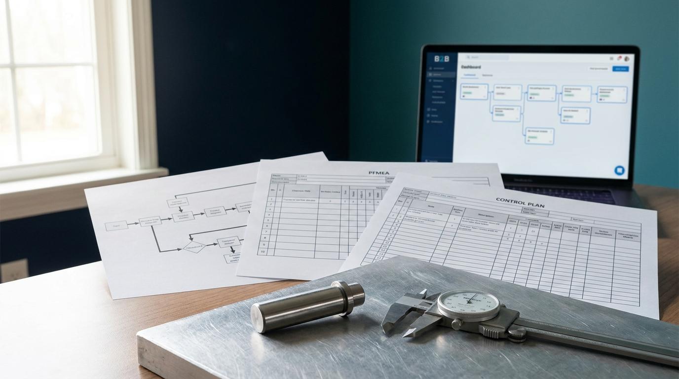
This is the intake problem behind the document cascade: a Process Flow, PFMEA, and Control Plan can only stay in sync with each other if they start from the same structured data. If that data enters the system as a human's manual reading of a drawing, retyped three different ways into three different documents, the seams reappear at the very first step. Blueprint Intelligence exists to close that seam, the one between the drawing and the first document that uses it.
What actually happens when you upload a drawing
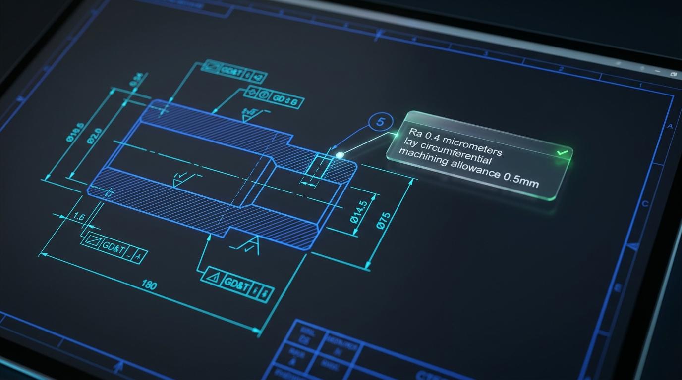
You upload the PDF or image to Blueprint Intelligence. The system reads it the way a quality engineer would, not as a block of text to OCR, but as a technical drawing with a specific structure: a title block, a field of dimensioned features, a set of GD&T feature control frames, material and process notes, and a list of referenced standards.
What comes back is not a summary. It is structured data, field by field:
- Dimensions. Every dimensioned feature, with its nominal value, its plus and minus tolerance, and its unit of measure, structured so it can go straight into an Inspection Plan measurement requirement.
- GD&T callouts. Feature control frames parsed into their components: the geometric characteristic symbol (flatness, concentricity, true position, profile, runout, and the rest of the ASME Y14.5 vocabulary), the datum references, and the tolerance zone. The frame is captured as a structured object, not a picture of one.
- SC/CC and diamond characteristics. Safety Critical, Critical to Quality, and diamond-marked characteristics are identified and flagged automatically as their own field, not left for someone to notice on a second read of the drawing.
- Material and process specs. Alloy grade, hardness requirement, heat treatment, surface finish, and coating callouts, structured the same way.
- Drawing notes and referenced standards. General notes, zone-specific notes, and any referenced ASTM, SAE, or customer specification.
Every extracted field carries a confidence score. On a sample drawing we use internally, EML2322L-020-R1, a wheel hub print, the extraction reads a 47.2 mm dimension at 99% confidence, a plus or minus 0.05 mm tolerance at 98%, a Ra 1.6 surface finish at 95%, a position callout of 0.10 mm diameter referencing datums A, B, and C at 97%, 4140 alloy steel at 94%, an HRC 28 to 32 heat treatment range at 91%, and the Rev C drawing revision itself at 99%. That is a real drawing we test against, not a marketing mockup, and it is representative of what a customer drawing produces.
None of this is a locked result. Every extracted characteristic, dimension, and note is presented for review before it goes anywhere. You can edit a value, correct a misread callout, or remove a field the AI flagged that does not belong. The extraction gives you a structured starting point. The engineer still signs off on what is correct.
Why the SC/CC flag is the important field
Most of what Blueprint Intelligence extracts is convenience: it saves retyping dimensions that were always going to be on the drawing anyway. The SC/CC and diamond flag is different. That single field is what tells the downstream documents where the risk actually is.
When a characteristic is flagged Safety Critical or Critical to Quality on extraction, that classification carries into the PFMEA and drives the severity rating on the associated failure mode. IATF 16949 Clause 8.3.3.3 requires an organization to identify special characteristics and address them through the product and process design, and AIAG-VDA FMEA scoring treats special characteristics as a floor on severity, not a suggestion. If the classification only exists in someone's memory of what the drawing said, it depends on that person still being on the project when the PFMEA gets built. If it exists as a structured field attached to the characteristic itself, it survives the handoff.
The same is true for material specs. A heat treatment or surface finish callout extracted from the drawing appears as a process parameter when the Control Plan is generated, so the control method is written against the actual spec on the print, not a remembered version of it.
From Part Library into the cascade
Extracted characteristics do not stay in Blueprint Intelligence. They save to your Part Library, and from there they feed document generation directly. When you generate a Control Plan, a PFMEA, an Inspection Plan, or a Process Flow for that part, the AI pulls from the extracted data to pre-populate the document:
- Dimensions and their tolerance bands become Inspection Plan measurement requirements.
- SC/CC flags drive severity ratings on the corresponding PFMEA failure modes.
- Material and process specs appear as process parameters on the Control Plan.
- GD&T datum references and tolerance zones carry into the characteristic definitions the Control Plan and Inspection Plan both use.
This is the front half of the cascade we described in the PFMEA to Control Plan post: Process Flow feeds PFMEA feeds Control Plan feeds Inspection Plan. That post starts from an already-authored Process Flow. This is the step before it, where the drawing itself becomes the structured input the whole chain runs on. Skip this step, or do it by hand with a spreadsheet, and the cascade downstream is only as reliable as the transcription that fed it.
What comes off your plate
For an engineer receiving a new or revised drawing, five things change:
- No manual balloon log before the real work starts. The characteristics are already structured when you open the part.
- No missed feature control frame buried in a section view. Every GD&T callout on the page gets extracted, not just the ones on the main view.
- No re-keying material and process specs into three separate documents. They are attached to the part once and appear wherever they are needed.
- Special characteristics are flagged at intake, not discovered when the PFMEA gets built weeks later.
- A drawing revision does not mean starting the transcription over. Re-upload the new revision and review what changed against the prior extraction.
None of this replaces the engineer's judgment. It replaces the part of the job that was never judgment to begin with: reading a drawing you already understand and typing what you read into a second system.
What to check before you trust the extraction
Extraction accuracy is high on clean, well-formatted drawings, but it is not a substitute for a review pass. Before saving to the Part Library:
- Confirm every feature control frame on the drawing has a corresponding extracted GD&T entry, especially callouts inside section views or detail views, where confidence tends to run lower than on the main view.
- Check that datum references match the datum feature symbols shown on the drawing, not just the letters in the feature control frame.
- Verify SC/CC and diamond markers against the drawing's own legend. Customer-specific symbols vary, and a legend note is exactly the kind of thing worth a second look.
- Cross-check material and heat treatment callouts against the title block or a materials note if the drawing splits that information across the page.
This is the same review discipline you would apply to a manually ballooned drawing. The difference is that you are reviewing a structured starting point instead of building one from a blank sheet.
Where this fits in a PPAP submission
Blueprint Intelligence output touches PPAP Element 1, Design Records, directly, since the extracted dimensions, tolerances, and characteristics are what a Design Record submission is built from. It also feeds Element 5 (Process Flow), Element 6 (PFMEA), and Element 7 (Control Plan) indirectly, through the Part Library data those documents are generated from. If you are running Blueprint Intelligence GD&T extraction alongside Build's document cascade and a Package submission, the drawing intake step and the submission gap analysis are checking the same underlying characteristic list, not two separate sources of truth.
Frequently asked questions
Does Blueprint Intelligence read scanned drawings as well as native PDFs? It processes both PDFs and images. Extraction confidence is generally highest on clean, high-resolution native PDFs and clear scans; a low-resolution photo of a print will produce lower confidence scores on fine GD&T text and should get a closer review pass.
What GD&T symbols does it recognize? Feature control frames covering flatness, concentricity, true position, profile of a surface or line, runout, and the standard ASME Y14.5 geometric characteristic set, along with the associated datum references and tolerance zones.
Can I correct an extraction before it becomes part of the record? Yes. Every extracted field is presented for review in the Build interface, and you can edit, add, or remove any characteristic, dimension, or note before saving it to the Part Library.
Does this replace the PFMEA severity rating decision? No. The SC/CC flag from the drawing informs the severity floor the way IATF 16949 8.3.3.3 requires; the engineer still owns the occurrence and detection ratings and the overall risk assessment.
What happens when a drawing revision changes? Upload the new revision and review the new extraction against the prior one. This is a manual comparison today, the same review you would run on a hand-ballooned revision change.
Uploading a print and getting back a structured, editable characteristic list is the starting point for the rest of the document cascade. Start a trial and run it against your own next incoming drawing.