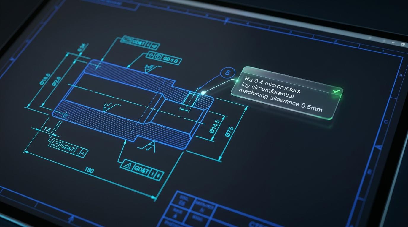
We just shipped a major upgrade to Blueprint Intelligence. The system now identifies what kind of drawing it is looking at, fully parses GD&T feature control frames, extracts thread callouts and welding symbols into structured data, and recommends the right gauges for each characteristic.
Here is what changed and why it matters for your quality workflow.
The Problem with One-Size-Fits-All Extraction
Our original Blueprint Intelligence was already effective. Upload a drawing, get structured characteristics with tolerances, SC/CC classifications, and drawing notes. It worked well for machined parts with linear dimensions.
But engineering drawings are not one-size-fits-all. A welded assembly carries different critical information than a sheet metal bracket or a wire harness. A position tolerance with MMC and three datum references requires different treatment than a simple linear dimension. A thread callout like "M10x1.5-6g" carries structured information that should be parsed into its components, not treated as a text string.
We needed the system to understand the drawing, not just read it.
What's New: Domain-Aware Extraction
Drawing Classification
When you upload a drawing, the system now classifies it first. In milliseconds, it determines:
- Manufacturing domain - Machined part, sheet metal, welded assembly, casting, or electronics
- Feature types present - GD&T, threads, welding symbols, surface finish callouts
- View count - Number of views, sections, and details on the sheet
This classification drives everything that follows. Instead of one generic extraction prompt, the system builds a domain-specific analysis tailored to what is on your drawing. A welded assembly gets deep weld symbol parsing. A machined part gets full GD&T and thread extraction. A sheet metal drawing gets bend callout analysis.
The result is dramatically richer extraction data with the same upload flow you already know.
Deep GD&T Parsing
This is the biggest change. Previously, GD&T callouts were captured as text strings like "Position 0.25 dia MMC to A, B, C." Useful, but not structured enough to drive downstream quality processes.
Now, every GD&T feature control frame is fully parsed into its components:
- Geometric characteristic type - All 14 types recognized (position, flatness, profile of surface, total runout, and more)
- Tolerance value and zone shape - Including diameter symbol detection
- Material condition modifiers - MMC, LMC, RFS properly identified on both the tolerance and each datum reference
- Datum references - Each datum with its own material condition modifier
- Composite tolerances - Two-line feature control frames detected with both tolerance levels
- Bonus tolerance flag - Automatically flagged when MMC or LMC makes bonus tolerance possible
Why does this matter? When you generate an inspection form from this data, the system now knows that a position tolerance at MMC to datums A, B(M), C requires bonus tolerance calculation during inspection. That is information your CMM programmer needs, and now it flows automatically from the drawing to the inspection plan.
Thread Callout Extraction
Thread specifications appear on nearly every machined part, and they carry dense information in a compact format. The system now parses thread callouts into structured data:
- Standard - UNC, UNF, metric coarse/fine, NPT, NPTF, BSPP, ACME
- Size and pitch - M10x1.5, 1/4-20, 3/8 NPT
- Class and fit - 6g, 6H, 2A, 2B
- Thread and hole depth - Including thru-hole detection
- Direction - Right-hand (default) or left-hand
- Helicoil/insert callouts - Flagged when present
When you generate an inspection form, the system can now recommend the correct thread gauge (Go/NoGo ring or plug) and flag Class 3 threads that need indicating gauges. No more manually looking up gauge requirements for each thread.
Welding Symbol Analysis
For welded assemblies, the system now reads AWS A2.4 welding symbols and extracts:
- Joint and weld type - Butt, tee, lap, fillet, groove (V, bevel, U, J, square)
- Weld sizes - Arrow side and other side
- Length and pitch - For intermittent welds
- Contour and finish - Flush, convex, concave with grind/machine finish
- All-around and field weld - Symbols detected
- NDE requirements - RT, UT, MT, PT, VT extracted from the symbol tail
- Specification references - AWS D1.1, D17.1, and others
This directly feeds weld inspection planning. When a weld symbol specifies RT (radiographic testing), that NDE requirement flows into your inspection form automatically.
Sheet Metal, Casting, and Electronics
The system also adds domain-specific extraction for:
- Sheet metal - Bend callouts (angle, radius, K-factor, direction), material gauge, grain direction, flat pattern dimensions, PEM inserts
- Casting and forging - Draft angles, parting line locations, X-ray inspection zones, machining allowances, as-cast vs. machined dimensions
- Electronics - Schematic components, connector pinouts, wire specifications, PCB features, IPC class requirements
New Tools That Work Without AI
Not everything needs an API call. We built three tools that run entirely on local logic with zero AI cost.
Standards Cross-Reference
When a drawing references "ASTM A36" or "AMS 2759" or "AWS D1.1", you can look up what that standard requires and what it means for inspection. The system includes over 40 common manufacturing standards with their key requirements and inspection implications.
Click "Look Up Requirements" and instantly see that AMS 2759 requires heat treat certs with actual temperatures and times, hardness test results, and pyrometry records. No more searching through binders or spec databases.
Measurement Plan Recommendations
For every characteristic extracted from a drawing, the system recommends the appropriate measurement method based on feature type and tolerance band:
- Tight tolerance (<0.01mm): CMM with dedicated fixturing
- GD&T position: CMM with datum reference frame setup
- Threads: Go/NoGo gauges, with indicating gauges flagged for precision classes
- Welds: Visual inspection plus the NDE method specified on the symbol
- Surface finish: Profilometer with cutoff length guidance
- SC/CC characteristics: Always CMM, always flagged for GR&R study
This is rule-based logic built from inspection planning experience, not AI-generated guesswork.
Revision Comparison
Upload two revisions of the same drawing and instantly see what changed. Added dimensions, removed features, tightened tolerances, new specs. Everything is highlighted with field-level diffs. Zero AI cost.
Smarter Balloon Linking
The ballooned drawing feature also received upgraded scoring. When the system matches balloons to inspection form characteristics, it now uses domain-aware signals:
- Thread balloons get boosted scores when matched to thread characteristics
- Weld balloons match preferentially to weld inspection items
- GD&T type matching: a "position" balloon scores higher against a "True Position" characteristic
- Multi-view deduplication uses view priority, preferring front view over section or detail views
What This Means for Your Workflow
The practical impact is simple: upload a drawing, get richer data, generate better inspection plans.
Consider a machined part with 15 GD&T callouts, 8 threaded holes, and references to AMS 2759 and ASTM A276. Previously, building the inspection plan required significant manual effort. Now:
- Upload the drawing
- Get structured GD&T details, parsed thread specs, and identified standards
- Look up what AMS 2759 and ASTM A276 require
- Generate a measurement plan with gauge recommendations
- Generate your inspection form with all the detail pre-populated
The extraction costs about three cents per drawing. Standards lookup, measurement planning, and revision comparison are free.
Try It Now
Blueprint Intelligence is available on all plans. Open Blueprint Intelligence in your dashboard, make sure Enhanced Analysis is toggled on, and upload a drawing. The more complex the drawing, the more you will see the difference.
We are building toward a workflow where the drawing is the quality plan. This update is a major step in that direction.